A drive shaft that hums at low speed and shakes the mounting frame at high speed is rarely a balance problem. Nine times out of ten it is a universal joint running at the wrong angle, or two joints phased wrong. The cross at the centre of that joint is a small forging doing a hard job — carrying full torque while pivoting on two axes, thousands of times a minute. This guide covers what the cross does, why the output shaft speeds up and slows down twice per revolution, the joint types available, and how to specify one. Krishna Forge forges universal joint crosses for industrial drives.
What a Universal Joint Cross Is
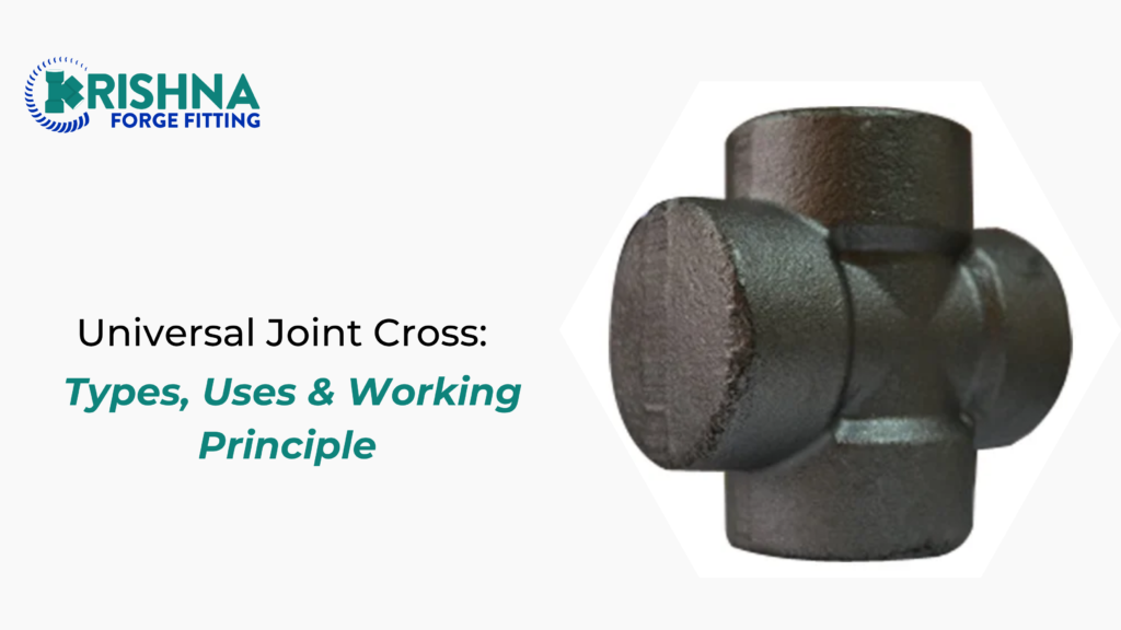
The cross — also called the spider, cruciform, or journal cross — is the four-armed forging at the heart of a Cardan universal joint. Four cylindrical journals extend at 90° intervals from a central body.
Two opposite journals sit in the driving yoke. The other two sit in the driven yoke. That arrangement gives the joint two perpendicular pivot axes and lets it transmit torque between shafts that do not line up.
Parts of the Assembly
The Cross or Spider
The load-carrying core. Journal diameter and length set the torque rating of the whole joint. It is normally a forging, not a casting, because the grain flow through a forged journal is what resists the bending and shear the joint sees under load.
Yokes
Two U-shaped or Y-shaped members, one on each shaft, bored to accept opposing pairs of journals. Yoke ear stiffness matters more than most buyers expect — a flexing yoke unloads the bearing and the cups start to walk.
Needle Bearings and Cups
Each journal runs in a cup packed with hardened needle rollers, typically 1 mm to 3 mm in diameter. The needles take the radial load and reduce friction to almost nothing. The cup is retained by a snap ring, a staked lip, or an injected plastic ring depending on design.
Seals and Grease
A lip seal at the base of each cup keeps grease in and water and grit out. This is the weakest part of the assembly. Almost every premature cross failure starts with a torn or hardened seal, not a broken forging.
How a Universal Joint Cross Works
The Two-Axis Pivot
The driving yoke rotates the two journals it holds. The cross carries that rotation across to the other pair of journals, which drive the output yoke. Because each pair pivots independently, the joint transmits torque continuously while the shafts sit at an angle.
Power flows through the cross at every instant. The bearings only accommodate the small oscillating movement of each journal as the shafts swing through their angle.
Why Speed Fluctuates
Here is the part that surprises people. A single Cardan joint does not deliver constant output speed. Even with the input turning at a perfectly steady rpm, the output speeds up and slows down twice per revolution.
The magnitude follows the joint angle:
- At 10° operating angle — roughly 1.5% speed variation
- At 20° — around 6%
- At 30° — around 15.5%
That fluctuation is a torsional excitation at twice shaft speed. It is the source of most single-joint driveline vibration, and no amount of dynamic balancing will remove it. The only fixes are reducing the angle or adding a second joint.
Types of Universal Joints
Cardan / Cross Type
The standard cross-and-yoke joint with needle bearings. Simple, compact, high torque density, and rebuildable. It is the default for industrial drives, agricultural PTO shafts and vehicle propeller shafts.
Double Cardan
Two crosses joined by a short intermediate shaft. When the yokes are correctly phased and both joints run at equal, opposite angles, the second joint cancels the speed variation of the first. Output speed comes out very close to constant.
Phasing is where installations go wrong. The two yokes on the intermediate shaft must lie in the same plane. Assemble them 90° out and you double the fluctuation instead of cancelling it.
Constant Velocity
Ball-and-cage designs that keep the balls in the bisecting plane of the two shafts at all times, giving genuinely constant output speed at any angle within range. Standard on front-wheel-drive axles. More expensive, less rebuildable, and generally lower torque capacity for a given size than a Cardan cross.
Ball and Trunnion
Combines angular movement with axial sliding in one unit, so it handles shaft length change as well as misalignment. Common where the drive geometry moves under suspension travel.
Operating Angle Limits
A single Cardan joint runs mechanically up to roughly 35° to 45° before the yokes interfere. That is the physical limit, not the practical one.
Practical working guidance:
- Under 3° — the joint may not rotate enough to circulate grease through the needles, which causes brinelling. Very small angles can be worse than moderate ones.
- 3° to 15° — the healthy band for continuous-duty industrial drives
- Above 15° — expect noticeable vibration on a single joint; go double Cardan
- Near the mechanical limit — short-duty and low-speed only
That first point is the counter-intuitive one. A shaft aligned almost perfectly still needs a small working angle for the joint to survive.
Where Universal Joint Crosses Are Used
- Propeller shafts and drivelines in rear-wheel-drive vehicles and commercial trucks
- Agricultural PTO shafts, rotavators, sprayers and harvesters
- Rolling mill spindles and steel plant drives
- Textile machinery and paper machine drives
- Pump and compressor jackshafts where the driver and driven unit cannot be co-axial
- Steering columns and control linkages
- Machine tool feed drives and instrumentation
Materials and Manufacturing
Crosses are normally hot forged from alloy steel — 20MnCr5, 20CrMnTi and AISI 4140 are common — then machined, case hardened and ground on the journals.
The sequence matters:
- Forging aligns grain flow along the journal axis, which is where the bending stress runs
- Case hardening gives a hard journal surface for the needles to run on, over a tough core that resists shock
- Grinding sets the journal diameter and surface finish; needle bearings are unforgiving of a rough or out-of-round race
- Case depth is the specification most often left off enquiries and most often responsible for early spalling
A machined-from-bar cross with no case hardening will look identical and fail in a fraction of the time.
Advantages and Limitations
Advantages
- Handles angular misalignment that no rigid coupling can
- High torque for its size
- Simple, low cost, and rebuildable in the field
- Tolerates shock loading well
Limitations
- Speed fluctuation on a single joint
- Needs periodic greasing on most industrial designs
- Cannot accommodate axial movement unless a slip joint is added
- Bearing life falls sharply as operating angle and speed both rise
Failure Modes and Maintenance
- Torn seals — the usual first cause. Grit gets in, needles score the journal.
- Brinelling — indentation of the journal surface from tiny operating angles or shock without rotation.
- Spalling — flaking of the hardened case, from overload or insufficient case depth.
- Yoke ear cracking — from excessive angle or a shaft that has been shortened without regard to the joint.
- Cup walk-out — a retaining ring failure that lets the cup migrate. Loud, sudden, and destructive.
Grease at the interval the drive’s duty demands, not the calendar. High-angle, high-speed, wet or dusty duty needs far more frequent service than a clean indoor drive.
How to Specify a Cross
- Journal diameter and overall span across journals — the two dimensions that define fit
- Torque rating, continuous and peak
- Operating angle and shaft speed
- Retention type — snap ring, staked, or injected
- Material grade and case hardening depth
- Grease fitting — with or without, and where it sits
- Sealing class — standard, or heavy-duty for wet and dusty service
FAQs
Why does my drive shaft vibrate at high speed but not low speed? Almost certainly the speed fluctuation of a single Cardan joint. The excitation happens at twice shaft speed, so it climbs with rpm and often hits a resonance in the mounting frame. Reduce the operating angle or move to a properly phased double Cardan.
What operating angle should I design for? Between about 3° and 15° for continuous industrial duty. Below 3° the joint may not rotate enough to circulate grease, which causes bearing brinelling. Above 15° on a single joint, vibration usually becomes a problem.
Is a forged cross really better than a machined one? Yes, and the difference is in grain flow. Forging aligns the steel’s grain along the journal, where the bending stress runs. A cross machined from bar stock cuts across that grain and loses fatigue strength exactly where it is needed.
How often should a universal joint be greased? It depends on duty, not on a fixed calendar. High speed, high angle, wet or dusty conditions can call for weekly greasing; a clean, low-angle indoor drive may run for months. Grease until fresh grease appears at all four seals.
Can I replace just the cross and keep the yokes? Usually yes, provided the yoke bores are still round and within tolerance and the ears are not cracked. Check both before reassembly — fitting a new cross into a worn yoke bore is a short-lived repair.
The Bottom Line
The cross is a small forging carrying the whole load of the drive. Get the operating angle into the healthy band, phase double joints correctly, keep the seals intact, and specify a properly forged and case-hardened cross — those four things account for most of the difference between a joint that lasts years and one that fails in a season.
Krishna Forge manufactures universal joints and universal joint crosses alongside its full range of industrial fittings, forged from quality-checked raw material with the dimensional control and inspection that torque-carrying parts demand.
Send us your journal dimensions, torque and operating angle. Get a quote from Krishna Forge and put a cross in your drive that is built for the load.
